'Hands-on Help for SMEs' and Smart Technical People'
Limits Fits and Tolerances
Definitions, Selection & Understanding How it all Works for Practical Use
The subject of Limits Fits and Tolerances can sometimes be a little confusing for practising engineers and technicians. On this page we demystify the topic and provide crystal clear information to increase your understanding. A limits, fits and tolerance calculator is also provided for practical assistance. Additionally, investing in modern CAD training to accurately communicate your precision engineering decisions also makes sense. Ultimately it's about you having the information you need to 'get it' and get on.
In order to understand the terms, a useful succinct definition is provided by McGraw Hill:
'The extreme permissible values of a dimension are known as limits. The degree of tightness or looseness between two mating parts that are intended to act together is known as the fit of the parts. The character of the fit depends upon the use of the parts. Thus, the fit between members that move or rotate relative to each other, such as a shaft rotating in a bearing, is considerably different from the fit that is designed to prevent any relative motion between two parts, such as a wheel attached to an axle'.
Tolerance on the other hand is the total amount that a specific dimension is permitted to vary. It is the difference between the maximum and the minimum limits for the dimension.
We also cover Geometric Dimensioning and Tolerances (GD&T) fundamentals for your convenience.
Use the Limits, Fits and Tolerances info below either personally or with colleagues to learn, retrain, demonstrate and above all get on.
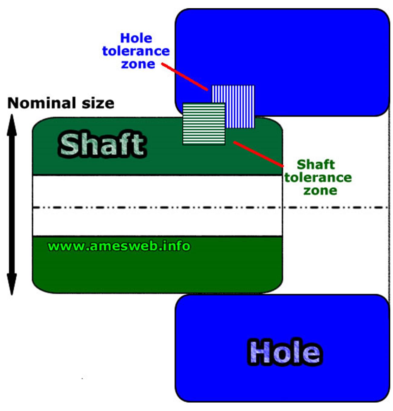
Fits and Tolerances: A comprehensive guide to the subject with clear descriptions of the key phrases. Tolerance dimensions are fully explained with examples and diagrams. Size designations including nominal, basic and actual sizes are covered. Additionally, interference, clearance and transition fits are illustrated with examples.
Other information includes shaft and hole systems, together with specification of tolerance examples. Definitions and terms related to metric limits and fits are listed. Other slides feature tolerances related to machining processes, cumulative tolerances and International Tolerance Grade (IT)
Practical explanation of Limits, Fits and Tolerances. Definitions, descriptions and clear explanations are provided to assist you. You will find useful information on shafts and holes, upper and lower deviation, grades of tolerance and numbering systems. Also clearance, interference and transition fits are covered. Text and diagrams provide a practical guide to the subject. This slideshow is a useful refresher for retraining or bringing new-comers up to speed.
Dimensional Tolerancing (inc. Geometric Tolerancing & Coordinate Tolerancing):
A comprehensice, yet clear explanation with worked examples of all key features. Extreme variations, sizes, form and tolerances are illustrated. Geometric characteristic symbols that apply to manufactured parts are comprehensively explained:
Tolerances of form shown include straightness, flatness, circularity and cylindricity. Tolerances of angularity covered include angularity, perpendicularity and parallelism. Tolerances of runout reveal circular runout and total runout. Tolerance of profile feature profile of a line and profile of a surface. Finally tolerances of location illustrate true position, concentricity and symmetry.
Geometric and coordinate tolerancing methods are compared with plenty of illustrations and examples of typical component features. Other areas comprehensively covered include material conditions and fixed and floating fasteners, again with worked examples. Exercises and quizzes test your understanding throughout, enabling the subject matter to be fully understood. Ideal for training and refreshing knowledge.
Limits and Fits, Selecting Size Tolerances (Courtesy of Geotol Pro): A good introduction into the topic. The main types of fit are covered including running & sliding fits, locational fits and force fits. The short video features an explanation of hole and shaft charts and how to use them, including permissible clearances potentially for lubricants.
Worked examples demonstrate how to use the chart to select an appropriate fit. Also how the standard can help you with examples of typical fits you may wish to select depending on the function you require. The video rounds off with examples you can try to test your knowledge.
GD&T Class for Production Engineering Application (Courtesy of Hexagon Metrology)
A new GD&T class focusing on ASME Y14.5: 1994 and 2009 standards, with emphasis on the practical application of these standards to real-world production measuring practices with PC-DMIS software. Beyond a mere theory course, this class focuses on practical take-home skills that the student can apply right away in a production manufacturing environment. Register for PC-DMIS GD&T Classes at: http://HexagonStore.com
Allowances MMC and LMC (Courtesy of the AutoCAD Channel): Maximum material condition and least material condition, core elements of geometric tolerancing. Crystal clear explanation of what this means for a machined component. The short video steadily describes the key ideas and the impact on allowances and tolerancing, together with what it means for the design engineer and the machinist reading the engineering drawing.
Why GD&T - Geometric Dimensioning & Tolerancing (Courtesy of Tec-Ease).
Solid explanation of why GDT knowledge and training is important for your SME manufacturing or engineering business. This includes how it impacts different teams throughout the organisation. Examples are given for the design, production and quality functions, demonstrating how it specifically benefits each team.
Poor understanding of GD&T is often one of the causes of engineering change orders and the subsequent drawing modifications all too common in many SMEs. These defects reduce competiveness and ultimately cost money, as parts are produced which are not fit for purpose.
Other areas covered include the importance of selecting appropriate GD&T early in the design cycle, together with the range of advantages this provides. Finally there is an introduction to the standard that governs GD&T in the US, together with a mention of the symbols, rules and vocabulary.
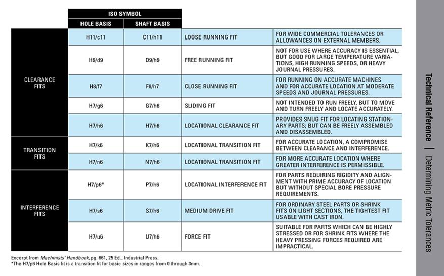
Quick Reference Hole & Shaft Fit Chart, with descriptions
Limits and Fits Calculator
A really handy limits and fits calculator (courtesy of Advanced Mechanical Engineering Solutions). Click and scroll down for the calculator. Simply input the nominal size you are after and click the calculate button. You'll instantly get a range of information including hole and shaft maximum and minimum sizes, upper and lower deviation for the hole and shaft, designation, type of fit, maximum allowable clearance and maximum interference. A schematic illustration of the fit is also produced to assist clarity.
In the left hand column limit and fit calculators are supplied for ANSI, Inches, ISO, Metric, as well as interference (press and shrink) fits and formulas for interference fits. This is a useful resource that provides you with assurance in what can be a tricky subject.
Back to Machine Shop Essentials
Try us! Search for any topic...
Home
Freelance Engineer Advice
Sustainable Manufacturing Help
Biggest Biz Problems & Solutions
Improving Manufacturing Productivity
Digital Manufacturing 4.0
Helping Your Business Thrive
Be the Best Engineer You can be
Essential Engineering Info
Lean Manufacturing Essentials
Product Development Essentials
CAD Engineering Essentials
Machine Shop Essentials
Skills, Career and Jobs
The Skills Shortage is Critical
Finding Your Ideal Engineering Job
Engineering Internships & Placements
Proactively Managing Your Career
Engineering Leadership & Management
Business & Industry
Business & Industry Essentials
Finance for Manufacturers
Marketing for Manufacturers
Emerging from Recession?
Affordable, No-Hassle Help
Familiar Training Frustrations
How to Access Supply Chains
No-Nonsense Manuals
Advice Manufacturing eBooks
Lean Manufacturing eBook
Product Development eBook
CAD Engineering eBook
Engineering Leadership eBook
Engineering Jobs eBook
Career Management eBook
State-of-the-Art Technologies
Cutting Edge Tech For SMEs
3D Printing Strictly for Industry
Automation & Robotics for SMEs
Future Manufacturing Initiatives
Virtual & Augmented Reality
3D Scanning & Reverse Engineering
Factory of the Future
High Impact Programme
Quick Implementation Plans
High Impact Programme Explained
Industrial Best Practice Examples
Advanced Security Industry
High-End Automotive Industry
Machine Shop Business Growth
Digital Manufacturing & Industry 4.0
Key Resources
Website Search
Celebrating Interesting Engineers
Sites that Matter!
Top Training Aid Slides
Amazon Book Store
Manufacturing Processes - Clips
How It's Made - Industry Clips
You get Free Technical Help Instantly
Get Your Free Report Now
Find a Manufacturer or Supplier
Profitable Remanufacturing for SMEs
Call for Case Studies!
Free Marketing for your Business
About Advice Manufacturing
Contact Us
About Us
Meet the Director!
Privacy Policy
Disclaimer
Site Map
Blog!
Advice Manufacturing Blog
Email
info@advice-manufacturing.com
No-Nonsense Manuals
See how our low cost, proven guides are transforming the fortunes of engineers like you and small manufacturing businesses just like yours...


Why not connect on LinkedIn? We are eager to grow our network of technical contacts, for mutual benefit...
FREE Report
Download now...

Manufacturing is important, right? So help to support it is Vital...
Why not let friends and colleagues know about Advice Manufacturing?...
The engineering world is changing quickly. We could all do with some help just to keep up. Get the word out in discussions and blogs. Forward links to web pages and articles. Who do you know who'd be interested?... Be Proactive!